


If the target region of interest on the cryo-ET grid is easily identifiable and has appropriate sample thickness, no further steps are necessary prior to data collection. However, if the region of interest is difficult to locate or too thick to image, then the specimen requires further processing. This chapter will introduce the fundamentals and practices of cryo-CLEM, cryo-ultramicrotomy, and cryo-FIB milling. These three methods contribute to specimen optimization for imaging at the microscope. For example, cryo-CLEM is used as a localization tool to cut down screening time and improve efficiency at the microscope, since the regions of interest on the grid are predetermined using fluorescent signals. Cryo-ultramicrotomy and cryo-FIB milling are both used on thick samples to transform them into thin slices, or lamellae, that can be imaged in the TEM. FIB-milling approaches are further divided into production of lamella of samples on grids, waffle FIB-milling, and cryo-Lift out. The following modules will focus on the main concepts of these techniques. Each of the workflows presented are examples for the method and not intended to be a one-size-fits-all approach, and, most importantly, these should be considered only when necessary.
One common challenge in cryo-ET is the identification of specific molecules or regions of interest in the vitrified samples due to the low signal-to-noise ratios. Immunohistochemistry cannot be performed on frozen samples and permeation and fixing of cells prior freezing may jeopardize native structures. Cryogenic correlated light and electron microscopy (cryo-CLEM) is quickly emerging as a leading method that allows inspection and analysis of the vitrified samples while maintaining structural integrity (Chapter 2).
Cryo-CLEM requires specialized equipment to correlate between images generated by light and electron microscopy, such as an upright fluorescent microscope equipped with long-distance objectives and a cryogenic stage, or an integrated fluorescent microscope in the FIB/SEM. There are advantages and disadvantages to either set-up:
| External fluorescence microscope | Integrated fluorescent microscope |
|---|---|
| Different objectives provide different magnifications | Only one magnification option during the experiment available due to space constraints |
| Open cryo-stage can introduce crystalline ice-contamination | In chamber imaging minimizes ice-contamination |
| Easy sample loading process, faster screening of grids | Cumbersome sample loading process, slower screening of grids |
| Final lamella can be viewed but it involves an additional transfer step after milling | Direct visualization of samples during milling and final lamella to check for regions of interest |
| Confocal options | No confocal option available |
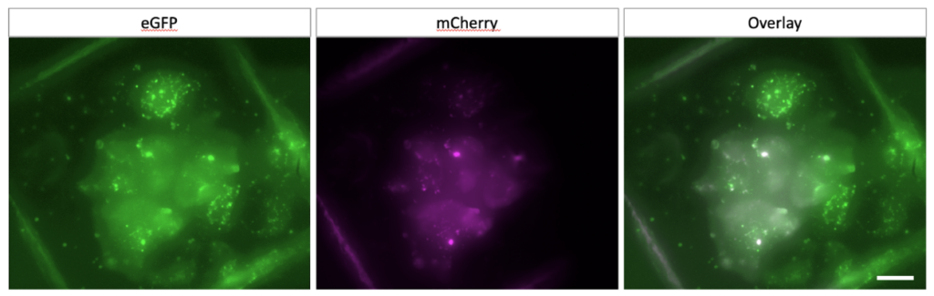
Generally, accessing labeled samples on vitrified cryo-EM grids using fluorescence imaging is helpful in that it can be also used to indicate sample quality.
Multiple fluorescent tags at different emission wavelengths can be expressed within the same specimen to enhance localization efforts.
Cryo-Focused Ion Beam (FIB) milling is an alternative technique to cryo-sectioning for thinning of samples for cryo-ET that is applicable to both HPF and plunge-frozen grids. As the name of the method implies, a focused ion beam (typically gallium) is used to thin, or mill, the sample into a thin sheet by blasting the unwanted regions away. The resulting sheet, or lamella, is typically 100-200 nm thick. FIB-milling is rising in popularity because it creates an accessible way to generate imageable areas from thick samples.
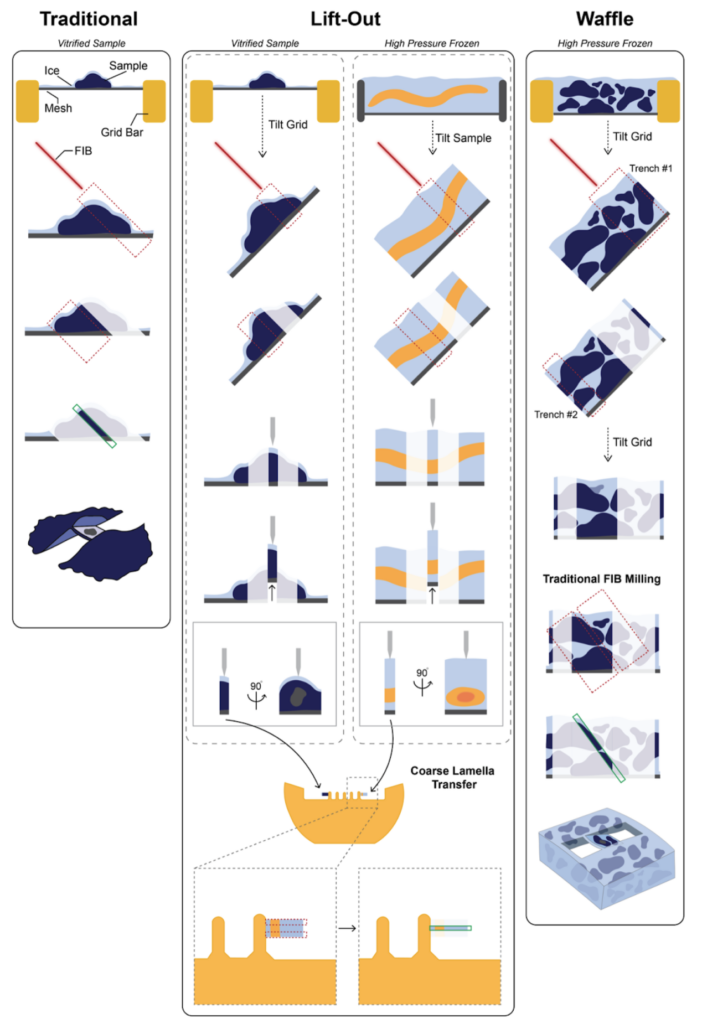
Substantial method development enables FIB-milling from specimens on grids to high pressure frozen bulk samples or tissues. To achieve the lamella for each case, the approach is different for each but all share the concept of ion beam milling: traditional cryo-FIB lamella preparation, waffle FIB-milling and cryo-Lift out.
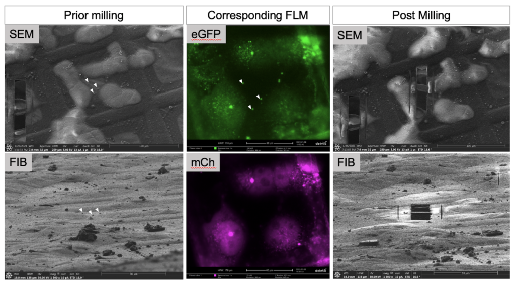
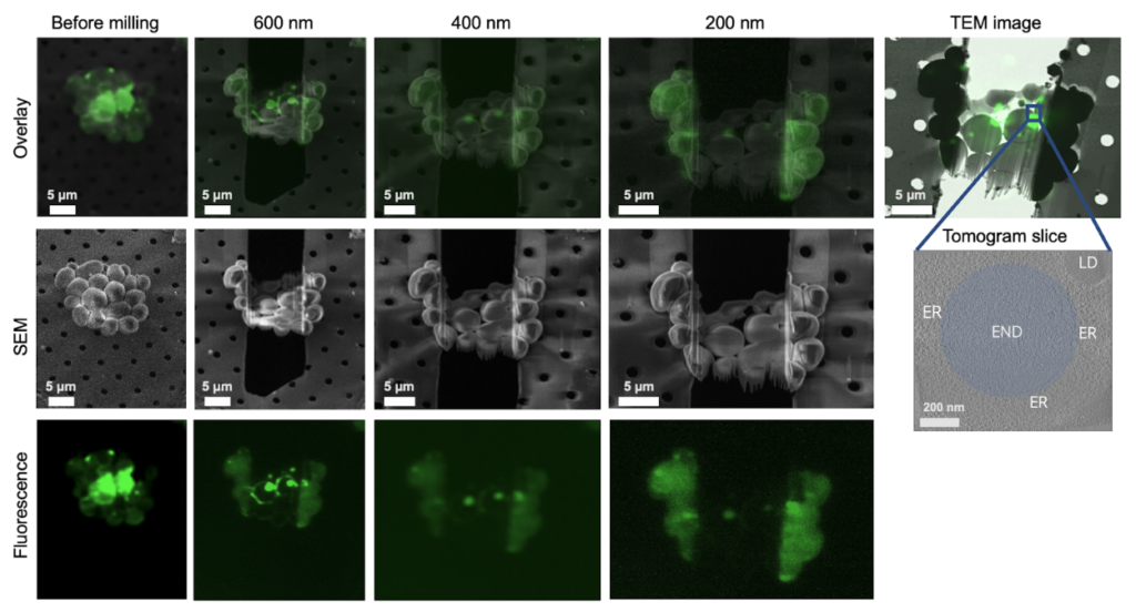
The simplest FIB-milling workflow will generally begin with identifying the region of interest on the grid and confirming the presence of the regions of interest with fluorescence, if needed. After the target region has been identified, the milling process is ready to begin The FIB-mill instrument operates under cryogenic temperatures, and is equipped with a dual beam: a focused ion beam (FIB) and a scanning electron beam (SEM), each of which provides distinct pictures of the sample. The SEM provides the overall landscape from a top-down view, almost like a topographic map and helps identify cell locations, while the FIB is oriented to the sample from a shallow angle between 5-15° to the grid surface.
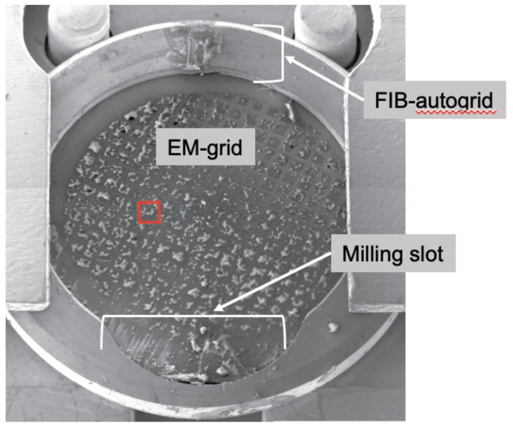
To allow for the shallow FIB angle, the grids need to be clipped into a specialized autogrid holder that allows them to be milled, since it has an indented rim for the shallow ion beam, while being compatible with imaging on the stage of the electron microscope.
The loading process of the FIB/SEM requires a specialized transfer system to keep the sample at cryogenic temperatures, free of crystalline ice contamination and allow for entry of the imaging chamber at vacuum.
A gas injection system (GIS) is used to deposit a thick protective layer of platinum onto the sample to protect it during milling, reduces charging during imaging and milling, and minimizes curtaining artifacts since it presents a continuous, dense layer to the ion beam. The scanning electron microscope allows for monitoring of the milling with a gentle, non-destructive electron beam. Usually lamellae are cut by removing bulk around the area of interest by moving the ion beam back and forth first, followed by a fine polishing step down to the final thickness. After the lamella are cut, a thin layer of inorganic platinum is deposited to improve electrical conductivity of the surface during tilt-series collection.
FIB milling happens gradually, as each layer of atoms is removed by a precise ion beam. An advantage of dual beam instruments is that the lamella can be cross checked with its integrated fluorescence microscope to confirm that the region of interest is still present, so no time is lost screening at the electron microscope during data collection.
The milling of lamellae from samples prepared with the waffle method requires a slightly different approach. Due to the way samples are prepared, the sample is very thick and instead of resting on top of the carbon support film, the sample is lodged deep in the grid squares. The method makes it accessible to image target samples with diameters ranging between nanometers to tens of microns. Due to the increase of sample density, larger lamellae of 10 x 25 µm can be created which can increase throughput substantially in comparison to traditional lamella which often have dimensions of approximately 10 x 10 µm.
To be able to efficiently prepare lamellae for waffle grids, two additional steps in the workflow are incorporated to remove the material ‘north’ and ‘south’ from the lamella, which creates two trenches. Lamella are very thin and thus fragile by design and it has been found that while remnants of material are needed to support the lamella, when the material surrounding it becomes too thick it is also rigid and lamella will break during handling of the grids. To relieve the stress, while preserving integrity during imaging, a notch can be milled on one side of the lamella to alleviate the tension problems comprising the second additional step.
For further details on the waffle method please refer to: Kelley et al. (2022) https://doi.org/10.1038/s41467-022-29501-3 and an excellent step by step protocol by Klycov and Bobe et al. (2022) doi: 10.21769/BioProtoc.4544.
When it is desired to determine ultrastructural features, molecular machines or macromolecules from whole organisms like C. elegans that can be vitrified through high pressure freezing (HPF, see Chapter 2) the orientation of the regions of interest might be predetermined. Similarly, cellular structures may always be arranged in a similar orientation in cells grown or frozen on grids. This may interfere with the analysis, since data for the oblique view are not readily available due to missing wedge artifacts (Chapter 1).
For small cells, like yeast or bacteria this issue can be mediated by using the waffle method, but for other systems including but not limited to whole animals like worms or entire tissues that do not fit inside a grid square and cells grown on grids, this presents a challenge.
To mitigate this problem, a thick lamella can be coarsely cut and removed from the environment and flipped perpendicularly through attachment to a new specialized half moon grid. The reoriented coarse lamella can then be polished and provides access to the previously obscured region mitigating the completeness problem. This system has been already in place for material science applications but presents a fairly recent development for biological sciences. Please refer to Schaffer et al. (2019) https://doi.org/10.1038/s41592-019-0497-5 and Kuba et al. (2020) doi: 10.1111/jmi.12939 for further information.
Although the techniques are very good when they work well and can produce ideal lamellae for the cryo-ET workflow, common issues occur. Although artifacts like curtaining, cracking and repositioning can be caused by milling, they can be avoided.
When samples are thick, or cells are clustered in close proximity to each other, they are at risk of not being fully vitrified but to contain crystalline ice. An easy way to shift the odds to success is to select single cells or small clusters, or, include cryo-protectants (see Chapter 2).
Another problem often found is “curtaining”, since the lamella appears to be wavy like a window curtain. Curtaining appears when the ion beam encounters different material during milling and removes sample at different speeds depending on the regions. This can be counteracted by using the GIS system to deposit a thick layer of platinum on the surface, which then presents as a uniform surface to the beam. Simultaneously, this layer prevents redeposition of milled away samples.
Tearing or ripping of lamella and hence loss of the specimen are also a frequent occurrence. These appear often with handling since lamella are very thin and fragile and suspended between thick material. The frequency of tearing increases with size of the lamellae or thickness of the specimen. To counteract ripping, trenches are often milled left and right of the lamella where it is still attached to the material, which allow for some flexibility during handling and transport. In addition, a notch is milled on one side of the lamella which also helps with survival.
The last common trouble to highlight is crystalline ice contamination. This refers to surface ice that is deposited onto the grid during transfer steps, especially when the grid may be exposed to crystalline ice while being handled in liquid nitrogen. This can occur during clipping grids into autogrid holders, loading them into a fluorescent microscope, the FIB/SEM or the TEM cassette. Ideally, each of these steps should be performed using fresh liquid nitrogen and in an environment with low humidity to minimize ice crystal formation.
For further reading and information on issues and challenges of cryo-lamella preparation, trainees are pointed to Schaffer et al. (2017) https://doi.org/10.1016/j.jsb.2016.07.010, Wagner et al. (2020) https://doi.org/10.1038/s41596-020-0320-x, and, Tacke et al. (2021) https://doi.org/10.1016/j.jsb.2021.107743.
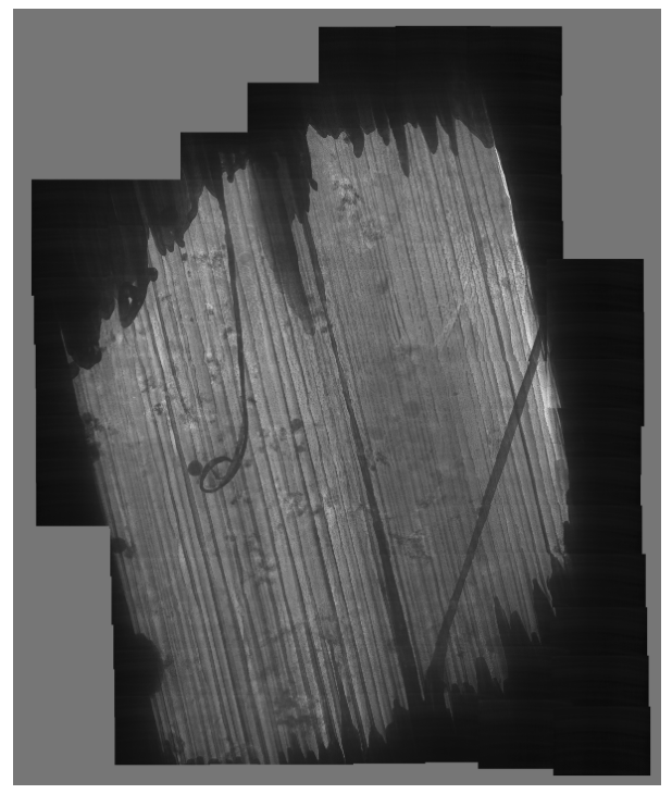
Lamella range in ice and particle quality and these are excellent examples demonstrating these issues and others.
Two out of three lamella in this sample were lost during transfer.
Lamella: Aquilos 2
Image: Arctica
Courtesy of Matt Johnson, University of Melbourne.
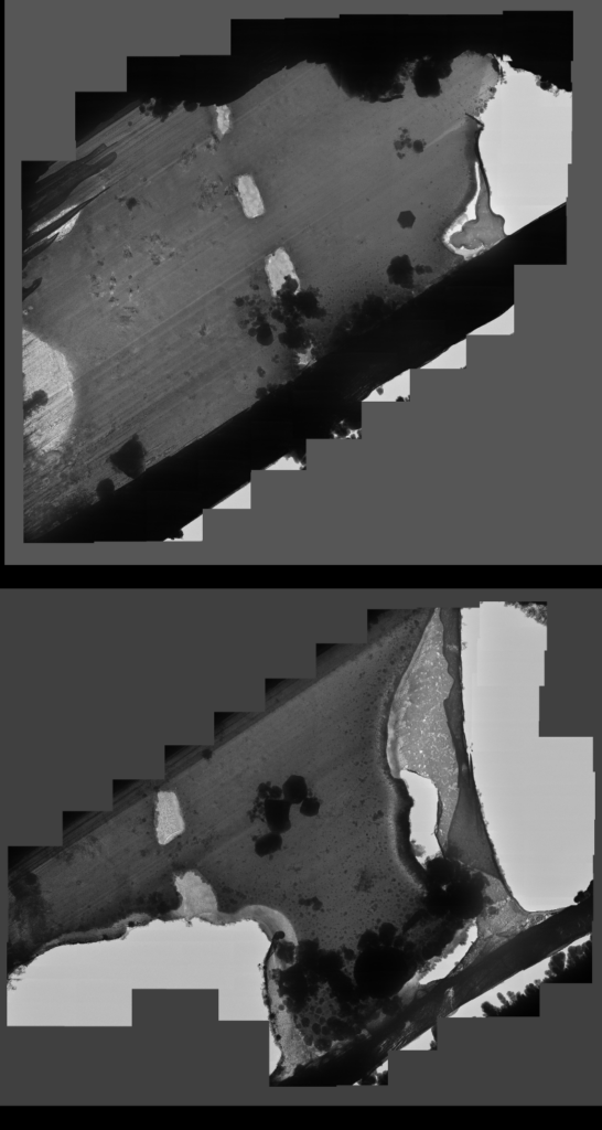
Lamella with crystalline ice contamination from transfer from dual beam to TEM. This lamella also shows curtaining from the milling process, appearing like bright lines along the lamella. The bottom of the lamella, which was produced using the waffle method, is obscured by the grid bar at this angle.
Lamella: Aquilos 2
Image: Arctica
Courtesy of Matt Johnson, University of Melbourne.
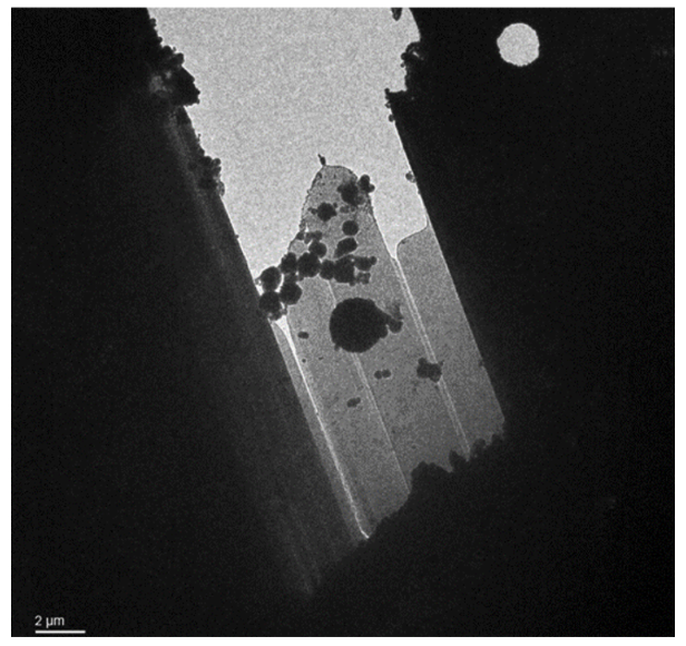
Curtaining from the ion beam is visible on the lamella. In addition, the lamella has been sliced in two by the ion beam, which is unusual. The cut occurred during a polishing step with an undertilt, where the stage shifted and the ion beam cut the lamella in half. Data could still be obtained from this sample.
Lamella: Aquilos 2
Image: Ion beam/ Aquilos 2
Courtesy of Matt Johnson, University of Melbourne.
The lamella surface is very rough, and shows extreme curtaining artifacts (stripes). This may have been caused by improper or insufficient polishing.
Lamella: Aquilos 2
Image: TEM
Courtesy of Maria Flores, UCLA.
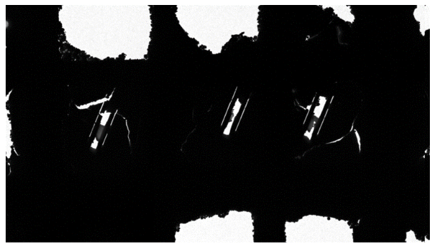
In this case, the time taken from course milling to polishing was long, which may have caused the square holes seen in the middle of the lamellae. The sample on the top was ripped during milling, when a beam shift hit the front lip of the lamella. In addition, ice contamination occurred when transferring the lamellae from the FIB-SEM to a cryo-confocal microscope.
Lamella: Aquilos 2
Image: TEM
Courtesy of Maria Flores, UCLA.
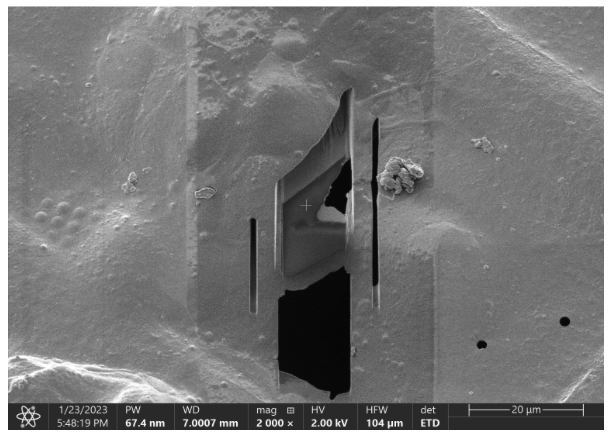
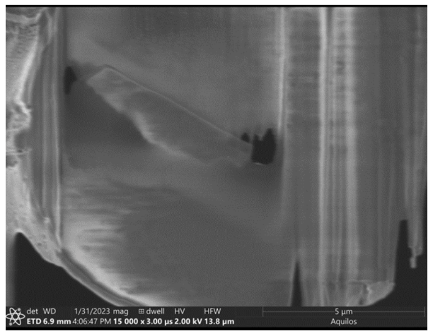
The lamella is torn. The lamella was milled too close to the grid bar (visible in image). Tearing may have been caused by ions bouncing from the bar to the sample.
Lamella: Aquilos 2
Image: Ion beam Aquilos 2
Courtesy of Maria Flores, UCLA.
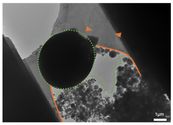
The lamella has multiple problems: the lamella is torn (orange lines) due to handling, crystalline ice is present as opaque circles and residual ice in the vacuum chamber of the FIB/SEM settled during the milling process (green dashed line), completely obscuring the region of interest (arrow heads).
Image adapted from: Tacke et al. (2021) https://doi.org/10.1016/j.jsb.2021.107743.
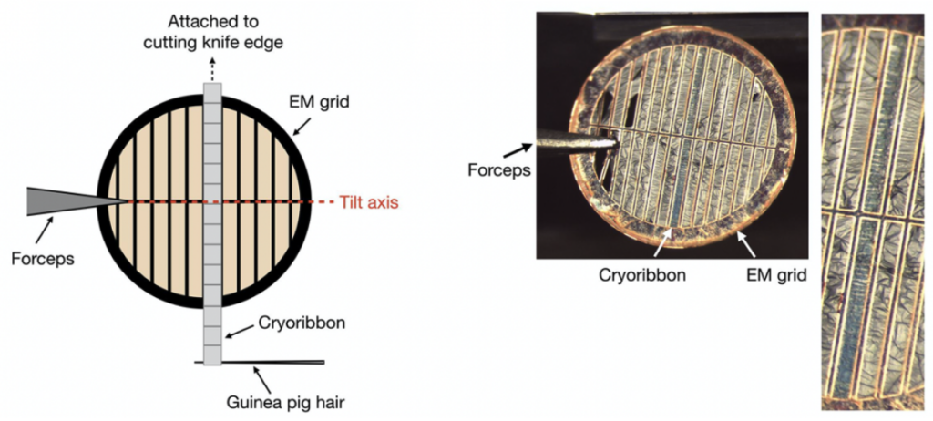
Some samples are too thick to be imaged directly by cryo-EM and require thinning. One method to achieve thin sections for high resolution imaging is cryo-ultramicrotomy, which can be applied to samples frozen by high-pressure freezing (HPF, see Chapter 2), but not to plunge frozen samples since these are too thin. Vitrified disks or blocks of tissue are preserved in a near-native state, which can provide high-resolution imaging of biological structures, large complexes, molecules, and their interactions. Thin sections, typically ~60-80 nm are shaved off the vitrified sample at -170° C using a diamond knife in the cryo-ultramicrotome, a process called cryo-sectioning. This method does not use chemical fixatives or staining agents in standard practice, which preserves the native structures within the sample. An advantage of ultramicrotomy lies in the generation of multiple slices of the same region that are then attached to an EM grid, so that multiple layers of the same region can be viewed and used for collection of tilt-series.
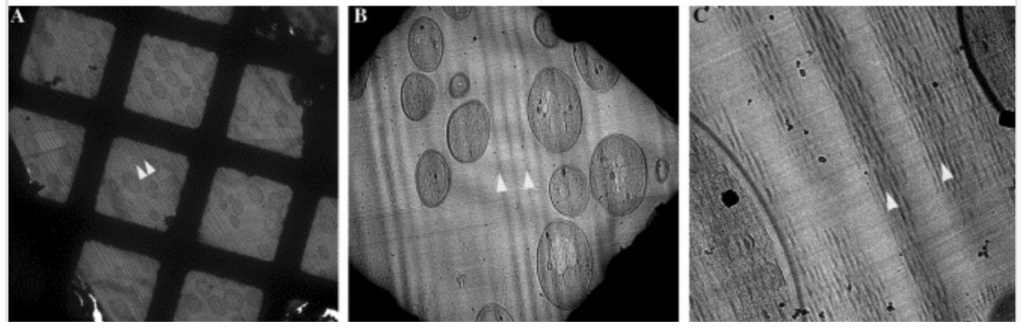
However, mechanical slicing by a diamond knife is susceptible to various artifacts, which become more severe as the sections become thinner. Such artifacts include curved sections, irregular compressions (chatter), and blade marks, especially on thinner sections (Ng et al. (2020); DOI: 10.21769/BioProtoc.3831) and at the beginning of training since this is a technically challenging method that needs considerable practice. Poor reproducibility caused by these artifacts becomes an issue when the tomograms need to be quantified. Artifacts observed during the FIB-milling process do not occur during sectioning with a diamond knife. Please see Richter et al. (1994) (https://doi.org/10.1016/0968-4328(94)90001-9) and Al-Amoudi (2005) (doi: 10.1016/j.jsb.2005.01.003) for more information.
Therefore, 3D reconstructions are often limited to descriptive results, except for a few examples (e.g. https://doi.org/10.1038/nature05994). An additional advantage of ultramicrotomy is that if the sections are transferred to the grid and thawed (Tokoyasu-style, doi: 10.1007/BF02473201) before they are imaged in the TEM, immunogold labeling can be performed to identify protein localization in each of the sections, while modifications to FIB-milled lamella are not possible.
There are several viable strategies to optimize samples for cryo-ET depending on the types of samples and the questions that are being asked. Cryo-ultramicrotomy and different approaches of FIB-milling each provide solutions to identify and zone in on target regions of interest, and create sufficiently thin samples to be penetrated by the electron beam during data collection. These methods have created new opportunities to access in situ structural biology through cryo-electron tomography at increasingly high resolutions. For more details and technical information, please check out excellent methods papers and reviews about FIB-milling (e.g., Wagner et al. (2020); https://doi.org/10.1038/s41596-020-0320-x and Rigort and Plitzko (2015); https://doi.org/10.1016/j.abb.2015.02.009). In addition, National Service Network for Cryo-Electron Tomography centers provide access and training for FIB/SEM instruments with fluorescent and lift-out capabilities, and cryo-fluorescent light and confocal microscopes that enable users to plan and conduct their experiments with high success rates due to expert advice (CryoET Centers).
© Copyright 2024