

After sample purification, the next step of the single-particle workflow is to prepare the cryo-EM specimen. The grid preparation process, often referred to as vitrification, is conceptually simple to understand: the aqueous sample is applied to a grid, the sample is made thin on the grid, and then the grid is plunge frozen at a time scale that prevents the formation of crystalline ice. Ideally, the ice layer should be just thick enough to support the particles. The particles should also be evenly distributed throughout the grid in a broad distribution of orientations, or views. Achieving the perfect cryo-EM grid, however, can be a tricky process and often requires extensive trial-and-error. In this chapter, we will cover the routine procedures used in cryo-EM grid preparation, common limitations, and emerging methods that overcome these limitations.
Plunge freezing of blotted grids is the standard method of cryo-EM grid preparation. The method was introduced in the 1980s by Jacques Dubochet and colleagues. A few microliters of purified sample are adsorbed onto a grid, blotted with filter paper to make a thin aqueous layer, and then plunge frozen into the cryogen. The vitrified ice should be as thin as possible to support the particle. Modern day instruments allow for controllable parameters that improve the reproducibility of vitrification. These parameters include temperature, humidity, blot force, and blot time. In general, the most commonly adjusted parameter to alter ice thickness is the blot time, which controls how long the filter paper is blotted against the grid. Although commercial instruments are the most common tool for vitrification, experienced users routinely achieve excellent ice quality using manual plunge freezing devices.
Attaining a biochemically pure sample is just half the battle towards a successful cryo-EM project. The other major bottleneck is finding the optimal conditions for preparing good cryo-EM grids. The ideal cryo-EM grid consists of particles that are evenly and richly distributed in a broad distribution of orientations throughout the holes of the support film. In reality, proteins can denature and aggregate; multi-component complexes can fall apart; particles can preferentially stick to the carbon layer and fail to partition into holes; particles can also adopt preferred orientations within the vitrified ice layer, thus limiting the number of unique views. Finally, some samples are poorly structured and are not amenable to image averaging. These common limitations prevent successful cryo-EM structure determination and require the user to go back-and-forth between the benchwork and TEM to optimize conditions.
This section provides an overview of common problems that are encountered during grid preparation and known strategies to overcome these challenges:
Orientation bias refers to the phenomenon where particles adopt a limited range of unique views, thus precluding 3D reconstruction. Recent studies demonstrate that the major cause of orientation bias arises from particle interactions with the hydrophobic air-water interface. Potential strategies to overcome orientation bias include treating samples with mild concentrations of detergent, to collect data using a solid support layer over holes, and to collect the data using a tilted stage. However, each of these strategies can introduce further complications as described below.
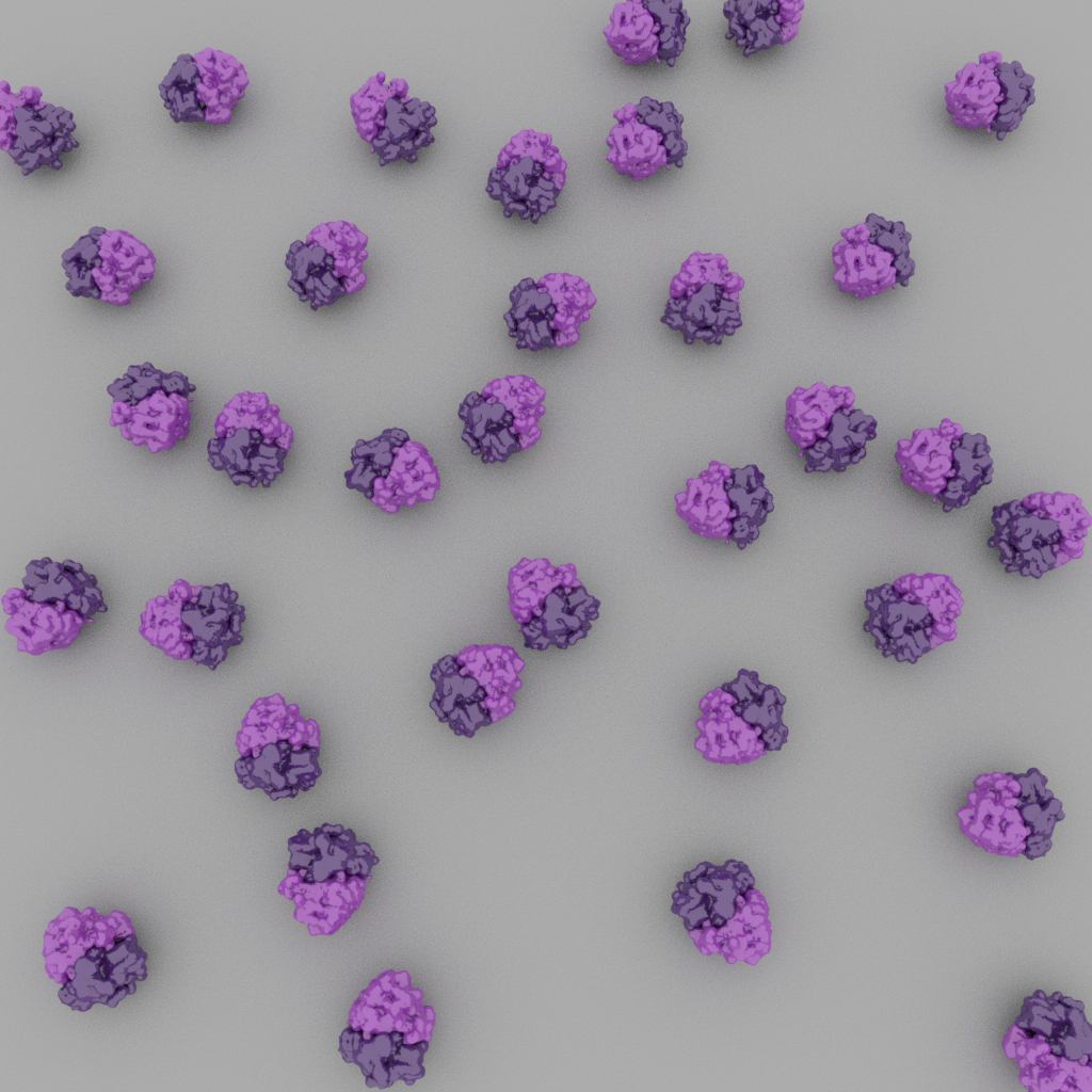
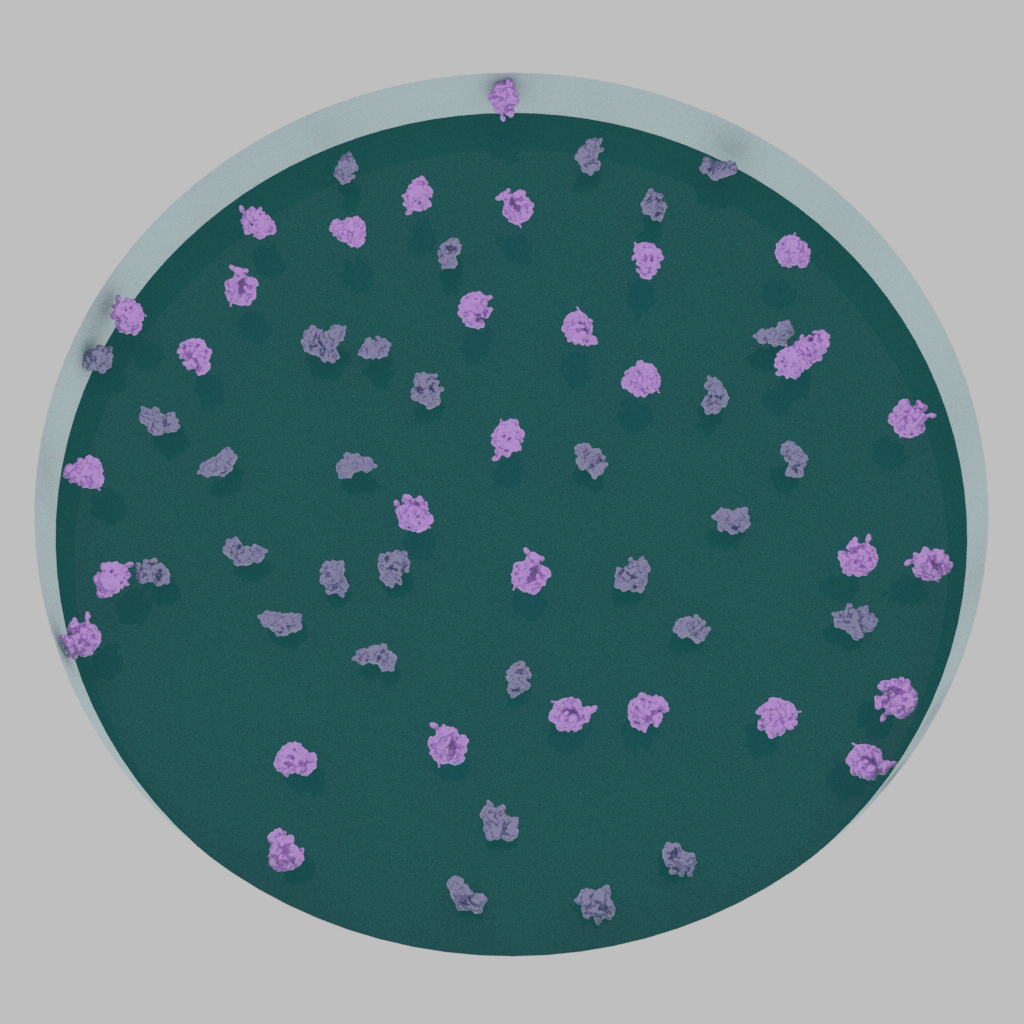
Particles may adopt preferred orientations on the cryo-EM grid, which will result in a limited number of unique projections (left). Ideally, particles adopt a broad distribution of orientations (right).
Solid support layer: One common way to achieve a different set of particle views is to introduce a thin solid support layer over the holes of the cryo-EM grid. Traditionally, a thin layer of amorphous carbon, typically 3-5nm in thickness, is deposited over a holey carbon grid. Sample application to these grids will cause particles to adhere to the carbon surface and shield them away from the air-water interface. However, ultrathin carbon tends to diminish the signal-to-noise ratio of particle images compared to images recorded over true holes and are therefore best used for larger particles. Note that particles may also adsorb onto the solid surface in a limited range of views.
One promising substitute to ultrathin carbon is graphene, which can be applied as a monolayer over cryo-EM grids. Monolayer graphene is sturdy and contributes virtually zero noise to cryo-EM images. Detailed methods for preparing graphene-based grids are described in the following sources:
| Graphene type | Reference |
| Monolayer graphene | Han et al., 2019 |
| Graphene oxide | Palovcak et al., 2018 |
| Functionalized graphene | Naydenova et al., 2019 |
| Functionalized graphene oxide | Wang et al., 2019 |
Finally, solid supports can be further modified to create so-called “affinity grids.” Such modifications include coating the support layer with antibodies, layering the grid with streptavidin 2D crystals, or introducing functional groups to the solid support. These affinity grids enhance particle adsorption and concentration on the grid and may be especially helpful for samples with low yields.
The following table lists a few examples of structures determined using various support layers.
| Particle | Resolution (Å) | Support Method | Databank Accession No. |
| 80S ribosome | 3.3 | ultrathin carbon | EMD-9240 |
| NDH complex | 3.1 | ultrathin carbon | EMD-0415 |
| Transcription factor IIH | 3.7 | ultrathin carbon | EMD-0452 |
| Separase complex | 3.8 | graphene oxide | EMD-3583 |
| Streptavidin | 2.6 | graphene | EMPIAR-10335 |
| Streptavidin | 3.2 | graphene | EMD-0689 |
| Fatty acid synthase | 3.1 | graphene | EMD-10420 |
| RNA polymerase II | 3.1 | affinity grid (streptavidin monolayer) | EMD-0633 |
| Tulane virus | 2.6 | affinity grid (antibody-based) | EMD-8252 |
Detergents: The addition of small amounts of detergents has proven useful in changing the distribution of particle views within the ice layer. This is thought to occur through the weakening of surface tension of the solution by the detergents, thereby affecting how particles interact with the hydrophobic air-water interface. The use of detergents generally requires highly concentrated samples (at least several mgs/ml) and careful optimization of ice quality. As described in Chapter 1, grids often need to be screened with different detergents because each detergent may have different effects on protein stability and function (Chen and Noble et al., 2018). The following table lists a few examples of cases in which the addition of detergents helped overcome orientation bias.
| Particle | Resolution (Å) | Detergent used | Databank Accession No. |
| Bacterial RNA polymerase | 3.8 | CHAPSO (0.5%) | EMD-7002 |
| NSF AAA+ ATPase | 4.4 | NP-40 (0.05%) | EMD-9103 |
| PRC2 complex | 3.5 | NP-40 (0.01%) | EMD-7335 |
| CRISPR-Cas13d | 3.3 | Amphipol A8-35 (0.1%) | EMD-9014 |
| TRiC-PFD complex | 6.5 | Octyl glucoside (0.1%) | EMD-0496 |
| INO80 complex | 3.8 | Octyl glucoside (0.05%) | EMD-4264 |
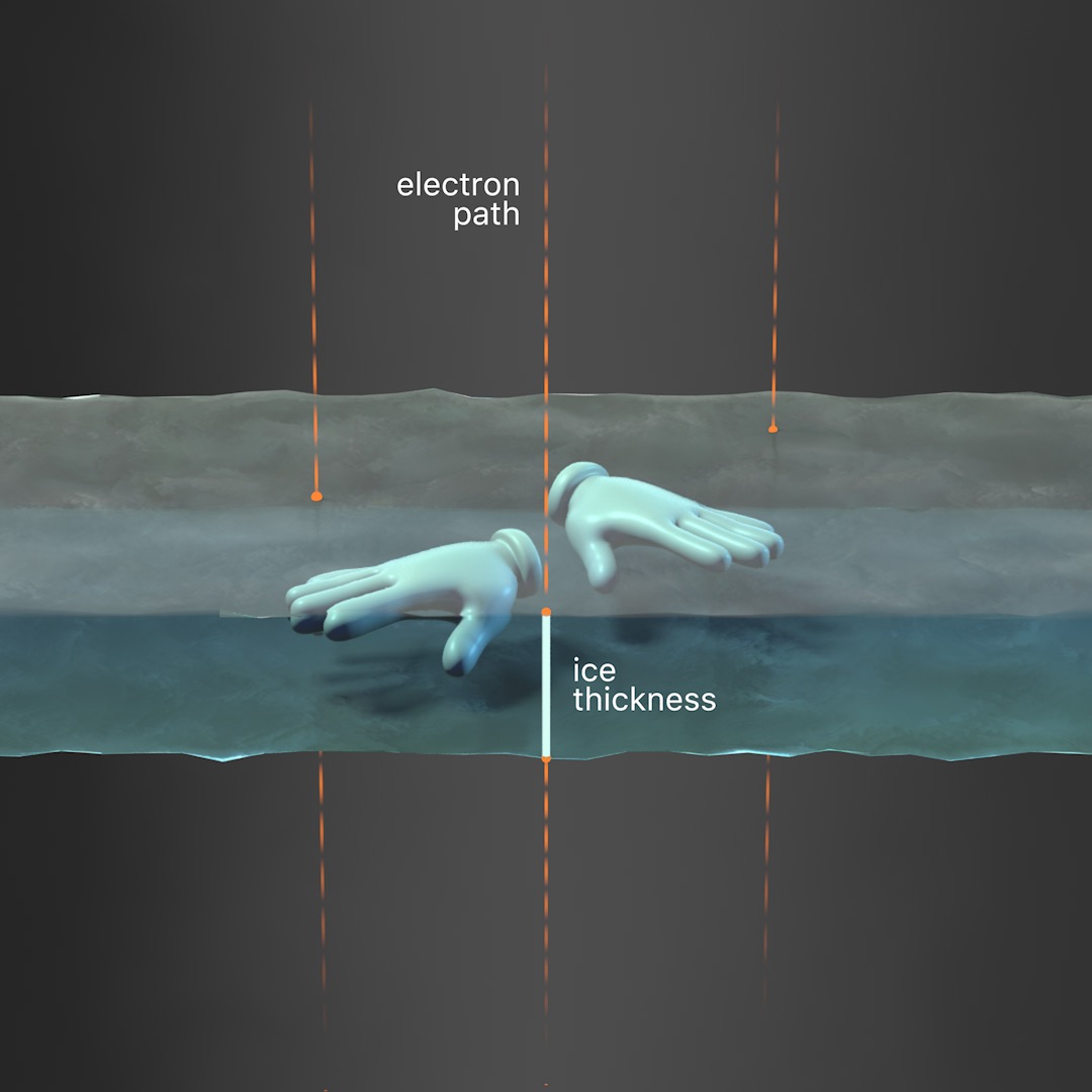
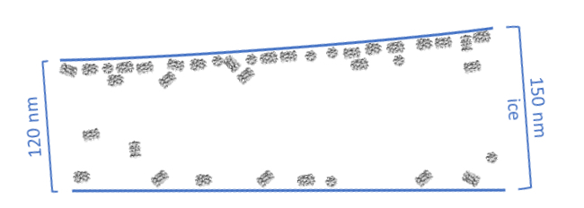
Tilted stage: Another method to resolve orientation bias is to directly tilt the TEM stage during data collection. Use the interactive module in this section to modify the stage tilt and follow its effects on ice thickness and particle views. Note that image quality may decrease due to thicker ice with increasing tilt angles and that particles may be in different focal planes within the same image. Particles that are closely packed together may also become overlapped with increased tilt angles.

Validation tools have also been developed to help researchers assess the quality of their orientation distribution (Tan et al., 2017) and estimate a suitable tilt angle for data collection (Naydenova and Russo, 2017). More discussion of these validation tools will be covered in Chapter 5, Image Processing. The following table lists a few examples of structures determined using tilted stages to overcome issues with orientation bias.
| Particle | Resolution (Å) | Tilt angle(s) used | Databank Accession No. |
| Hemagglutinin trimer | 4.2 | 40 | EMPIAR-10097 |
| Insulin receptor | 4.3 | 30 | EMD-7462 |
| Group II intron | 3.6 | 0-30 | EMD-9106 |
| P element transposase | 3.6 | 40 | EMD-20254 |
| Insulin degrading enzyme | 4.2 | 20-50 | EMD-7092 |
| MS2/F-pilus complex | 5.0 | 0-30 | EMD-0453 |
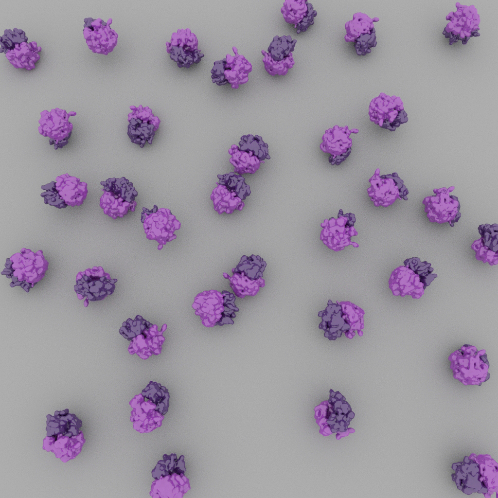
In some cases, particles fail to enter holes of the cryo-EM grid and instead are associated with the surrounding carbon surface. Improper particle partitioning therefore requires additional optimization steps as described below.
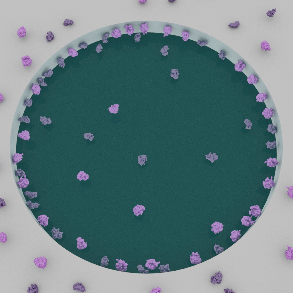
Particles may exhibit a preference to attach to the glow-discharged surface and fail to enter holes (left). Ideally, particles are covered throughout the holes (right).
Solid support layer: One common strategy to improve particle distribution is to use a solid support layer over holes, such as with ultrathin carbon or graphene as described above. This approach is perhaps the most straightforward way to achieve a uniform distribution of particles across the grid. Affinity grids can also be used to achieve the same effect and have the added benefit of increasing particle concentration on the grid surface.
Chemical treatment: Strong interactions between the negatively charged glow-discharged surface and particles can be addressed using different grid treatments. One longstanding method is to adjust the grid surface by introducing a poly-amine atmosphere during glow-discharge. In principle, this approach will give the carbon surface a net positive charge and can reverse the electrostatic effects of preferred carbon-particle interactions to repel particles into holes. This approach may also be used to coax particles to adopt a different set of views on solid surfaces.
Hydrophobic grids: Another viable strategy to drive particles into holes is to skip the glow-discharge procedure entirely. Due to the hydrophobic surface of non-glow-discharged grids, the sample droplet must be manually spread across the grid with the pipette tip. Note that ice quality is generally less reproducible with this method.
Multiple rounds of sample application: Particle density over holes can be increased by multiple sample applications (Snijder et al., 2017). This approach is achieved on the lab bench by using a procedure similar to preparing negative stain grids. The purified sample is applied to the glow-discharged grid, followed by blotting, and the process is repeated 1-4 times. After the final blotting step, the grid is then used in a normal plunge-freezing workflow.
As with all grid optimization steps, grids should be screened to confirm ice and particle quality. The following tables lists examples of different treatments used to optimize grid quality.
| Particle | Resolution (Å) | Grid treatment | Databank Accession No. |
| 20S proteasome | 3.5 | Amylamine | EMD-2981 |
| CCT complex | 4.0 | Polylysine | EMD-4489 |
| 60S ribosome | 3.5 | Hydrophobic | EMD-2811 |
| eIF2-eIF2B complex | 3.0 | Hydrophobic | EMD-0664 |
| Adenovirus | 3.7 | Multiple application | EMD-8471 |
| CRISPR-Cas13d | 3.3 | Multiple application | EMD-9014 |
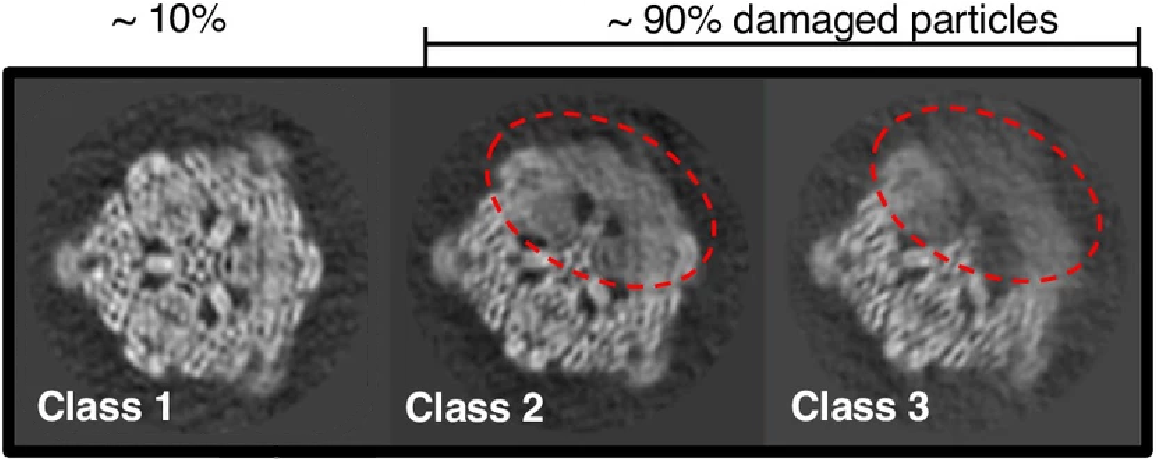
The most common problems in cryo-EM grids can be attributed to particle interactions with the air-water interface. During the grid preparation process, the blotting step greatly thins the sample layer and exposes particles to extensive collisions with the hydrophobic air-water boundary. These interactions are thought to be the primary cause of particle “sticking” to the edge of the ice layer, and single particle analysis of such particles indicates that their exposure to the interface causes protein denaturation (see figures below).
New instruments are now available or under development that aim to simplify and improve the grid preparation process. These instruments have in common that they omit the paper blotting step. The Spotiton instrument (licensed to SPT Labtech and available under the name Chameleon) uses a piezo dispensing device to apply nanoliter volumes of sample directly to self-wicking grids, and the grids are plunge frozen at a timescale that may “outrun” particle adsorption to the air-water interface (i.e., < 300 ms) (Dandey et al., 2018; Noble et al., 2018). EasyGrid also uses a piezo-electric drop dispenser (Gemin et al., 2024). Before vitrification, a pressure-wave is used to spread the sample on the grid after which it is vitrified using an ethane jet stream platform. A simplified, home-made device using piezo dispensing device that also freezes grids on a similarly fast timescale can also be assembled with readily purchasable components (Rubinstein et al., 2019).
Alternative to piezo dispensing, similarly small amounts of sample can be dispensed on the grid using dip pen technology or microcapillaries. The VitroJet (Ravelli et al., 2020) uses pin printing, using contact time and gap to control the amount of sample. Instead of plunging, it also uses a cold gas stream to rapidly jet-vitrify the grids from the center to the outside. Capillaries instead of pins are used in the cryoWriter (Arnold et al., 2017). Here a pump controls the amount of liquid to a grid, and vitrification is done by plunge freezing. A purification step can be integrated in the pipette, using magnetic tweezers (Schmidli et al., 2019).
In summary, the presented methods automate certain steps in the grid preparation, to eventually make sample preparation easier, improve the reproducibility of the grid quality, and reduce the amount of sample needed.
List of commercial cryo-EM grid preparation instruments
| Instrument type | Instrument name | Vendor link |
| Robotic blot & plunge freezer | Vitrobot | ThermoFisher Scientific |
| Robotic blot & plunge freezer | EM GP2 | Leica |
| Piezo dispensing device | Chameleon | SPT Labtech |
| Grid writing (capillary-based) | cryoWriter | cryoWrite |
| Grid writing (pin printing) | VitroJet | CryoSol |
Examples of home-made grid preparation instruments
| Instrument type | Description | Reference |
| Manual blot & plunge freezer | Home-made plunge freezer | Depelteau et al. Microscopy and Microanalysis (2020) Nguyen et al. J Vis Exp (2022) A vendor supplies the components needed to assemble the home-made device: Mitegen |
| Ultrasonic humidifying spray & plunge freezer | “Shake-it-off” device; self-wicking grids required. | Rubinstein*, Guo* et al. Acta Cryst. (2019) |
| Microfluidic spray & plunge freezer | Requires fabrication of microsprayer device. | Feng*, Fu* et al. Structure (2017) |
Preparing the ideal cryo-EM sample will usually require iterative trial-and-error in biochemical purification and grid vitrification. Some challenges can be readily addressed at the negative stain level, including particle homogeneity and sample yield; however, other challenges, such as particle partitioning into holes, are only apparent after preparing cryo-EM grids. Finally, issues with preferred orientation may not be obvious until after a cryo-EM dataset has been collected and processed into 2D classes. The strategies described in this chapter represent established approaches to overcome such obstacles. Exploring a combination of these strategies may be necessary to generate a successful cryo-EM dataset.
Additional resources
“Preparation of macromolecular complexes for cryo-electron microscopy”, Grassucci RA, Taylor DJ, Frank J. Nature Protocols (2007) — A detailed protocol for preparing holey carbon grids.
“Current outcomes when optimizing ‘standard’ sample preparation for single-particle cryo-EM”, Carragher et al. Journal of Microscopy (2019) — A commentary from a group of leading cryo-EM researchers that describe their experiences with optimizing cryo-EM samples.
The NIH Transformative High Resolution CryoEM initiative provides opportunities to receive proficiency-based merit badges. Currently, merit badges and detailed SOPs are offered for the following instruments:
Vitrobot: https://www.cryoemcenters.org/merit-badge/tfs-vitrobot-mark-iv/
Leica GP/GP2: https://www.cryoemcenters.org/merit-badge/leica-em-gp/
© Copyright 2024